Table of Contents
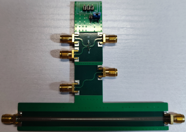
The Testing Fixture for 6-Lead QFN SPDT RF switch
Overview
I purchased several SPDT RF switches which manufactured by a Chinese listed company. The chip’s footprint is 1.0mm x 1.0mm x 0.45mm 6-lead QFN package. The manufacturer did not provide S-parameters. Thus, I had to design the fixture and measure the S-parameters by myself.
The Testing Fixture for 6-Lead QFN SPDT RF switch
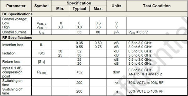
RF Specifications from the Datasheet
The De-embedded Measurements
S55 and S66 are original measurement data, S33 and S44 are de-embedded data:
| S44 is ANT | S33 is RF1 | RF1 ENABLED |
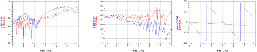 The measurement data conform to the Insertion loss and Return loss specifications in datasheet.
| S77 is RF1 | S88 is RF2 | ANT is terminated with 50 Ohm terminator | RF1 ENABLED |
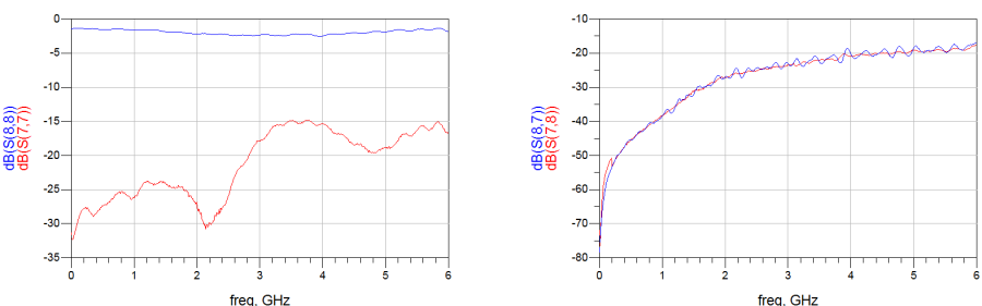 Unfortunately, the measurement data exceed the isolation specifications in datasheet.
Summary
The testing fixture meets my expectation for working within 0GHz to 6GHz. For the isolation, I think the IC may conform to the isolation specifications, because de-embedded algorithm cannot work with crosstalk problem. Crosstalk between the traces RF1 and RF2 on the PCB can downgrade the isolation.