Table of Contents
Meshtastic Mesh Device Station Edition
- Optimized RF Design for Maximum Coverage
Starts from 2022/May/31 to 2024/03/17 00:46 (Last Modification)
The Station G1 has been discontinued and has been replaced by the Station G2. Meshtastic Mesh Device Station G2 is an upgraded design of Station G1, using the latest ESP32 S3 MCU. As an RF research project, Station G2 also brings key updates in RF. The primary RF design goal of Station G2 is to improve the Lora receiving sensitivity by about 4dB based on a dedicated Ultra-Low Noise Figure LNA. Also increase the transmit power and improve Signal to Noise ratio of short data packets by designing the Fast-Transient DC-DC for 35dBm Lora PA.

Overview
 Meshtastic can send off-grid message using inexpensive hardware to create your personal mesh.
The Station Edition series is a compact Lora device with high power PA (Maximum TX Power: 35dBm@915MHz or 868MHz for Station G1 Edition), Rugged SMA Antenna Socket, rich external IO interface, wide input voltage range (8VDC-20VDC). This series aims to provide the best RF performance in all series with credit card size and rugged construction. Fixed-location base stations and vehicle-mounted base stations are typical application scenarios for this series.
For the firmware, all Station Edition devices come with pre-installed Meshtastic firmware. Meshtastic Mesh Device Station Edition G1 also had been supported by the official meshtastic repository on Github. More detials could be found in the The Latest Firmware section.
Dimension
| Item | Description |
|---|---|
| Size | 10cm*5.8cm*2.1cm |
| Color | Black |
| Weight | ~80g |
Typical RF Performance
| Item | Description |
|---|---|
| Lora Operation Frequency | US915MHz and EU868MHz |
| Lora RF Max Output Power | 35 dBm @ US915MHz (Station Edition G1) |
| Lora Power Amplifier Gain | 21.5dB @ US915MHz (Station Edition G1) |
| Lora Power Amplifier P1dB Point | 34.5 dBm @ US915MHz (Station Edition G1) |
| Lora Power Amplifier Noise Figure | 0.96dB @ US915MHz (Station Edition G1) |
| VSWR of Lora Stock Antenna | < =2 @ 915 MHz |
Typical Application Scenarios
Station Edition could be powered by either USB Type C (PD Protocol with minimum 9V2A is required, 15V2A is recommended due to the requirements of 12V Battery Docker) or 2Pins Socket (Pitch=2.5mm, 8VDC-20VDC, 2A minimum).
Wide voltage input makes the Station Edition ideal as an vehicle-mounted base station and powered directly from the in-vehicle 12V system. The USB Type C power input allows the device to be easily powered by a USB Type C adapter which supports the PD protocol.
Ability to increase transmit power makes it possible to balance communication distance and communication speed. For low power meshtastic devices, usually necessary to set the modem to Long/Slow to obtain the required communication distance, but when using this setting, the communication speed will be very slow, and the continuous sending of messages will also cause timeouts. By increasing the transmit power, we can set the modem to Long/Fast or even Medium/Fast to get a similar experience to Internet-based instant messaging software.
More information about modem setting: https://meshtastic.org/docs/settings/config/lora
Hardware
Schematics
| Schematics for 12V Battery Docker | meshtastic_mesh_device_station_edition_12v_battery_docker_28_jul_2022.pdf | Version: 28 Jul 2022 |
| Schematics for Station Edition G1 | meshtastic_mesh_device_station_edition_12_jun_2022.pdf | Version: 12 Jun 2022 |
PCB (Station Edition G1)

| No. | Description |
|---|---|
| 1 | ESP32 WROOM |
| 2 | Semtech SX1262 Lora Transceiver |
| 3 | Lora Power Amplifier |
| 4 | RF Switch |
| 5 | SMA Connector for Lora Antenna |
| 6 | USB Type C Socket |
| 7 | CH9102F USB to UART Bridge |
| 8 | Power Input Socket (8VDC-20VDC), 1*2P, Pitch=2.5mm |
| 9 | 7.5V DCDC |
| 10 | 3.3V DCDC |
| 11 | GPS and Notification Extension Socket, 1*5P, Pitch=1.5mm |
| 12 | IO Extension Socket, 1*10P, Pitch=1.5mm |
| 13 | LV (Low Voltage) LED Indicator |
| 14 | HV (High Voltage) LED Indicator |
| 15 | 1.3 Inch OLED Screen |
| 16 | User Button |
Power Status
| LV LED (Red) | HV LED (Green) | Description |
|---|---|---|
| ON | OFF | 3.3V DCDC is working normally, but 7.5V DCDC is not working. Generally, this status indicates the device is powered up by using USB2.0/3.0 which does not support 9V USB Type C PD protocol. For this status, everything should work normally, except the Lora PA. The firmware can be flashed into the device through Type C Port in this status. |
| ON | ON | Both 3.3V DCDC and 7.5V DCDC are working normally. Generally, this status indicates the device is powered up by either 9V USB Type C PD protocol or 12V Battery Docker. For this status, everything should work normally. |
Mechanical Design
Similar as Nano Edition, the Station Edition is also constructed by stacking up PCB boards.This method offers a good balance of cost and mechanical strength. The Station Edition employs an aluminum substrate PCB (sliver) as heat sink for high power lora PA. Nonelectrical conductivity high performance thermal grease is applied between the heat sink and the main PCB.

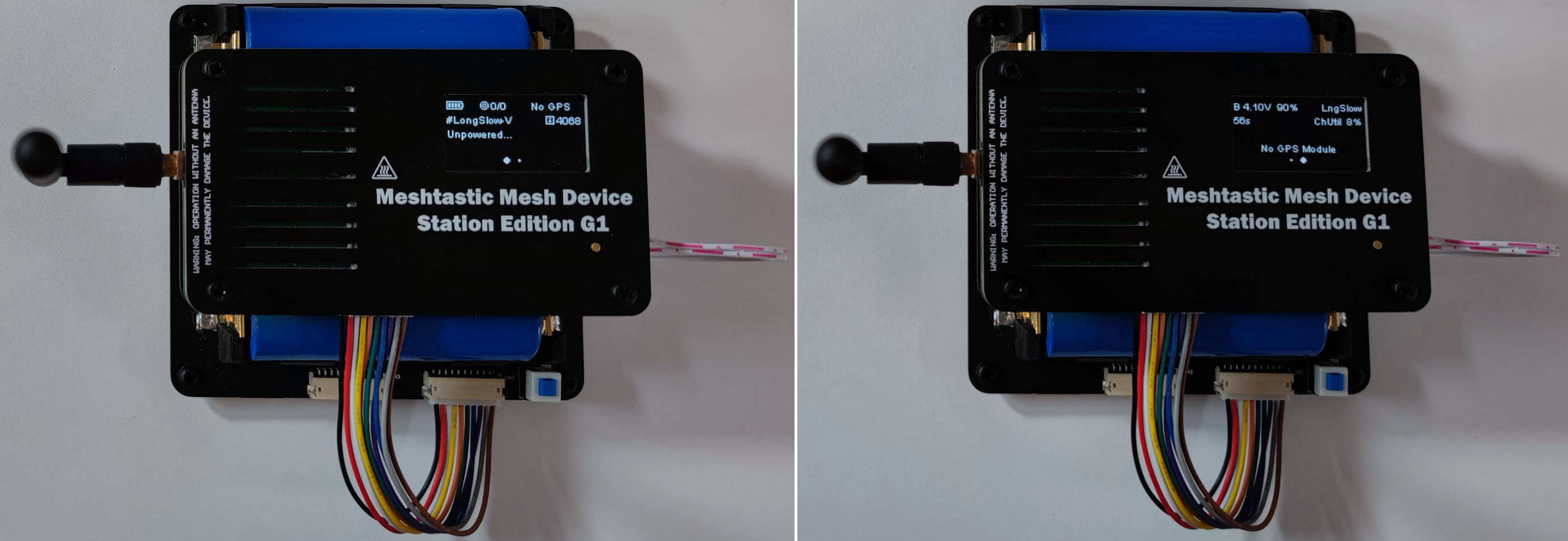
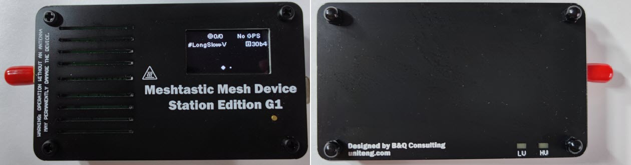 Front Side and Bottom Side of the case.
RF Design - Lora (Station Edition G1)
TX PA and Antenna
Conduction Test
Instrument Setup and Device Under Test (DUT) configuration
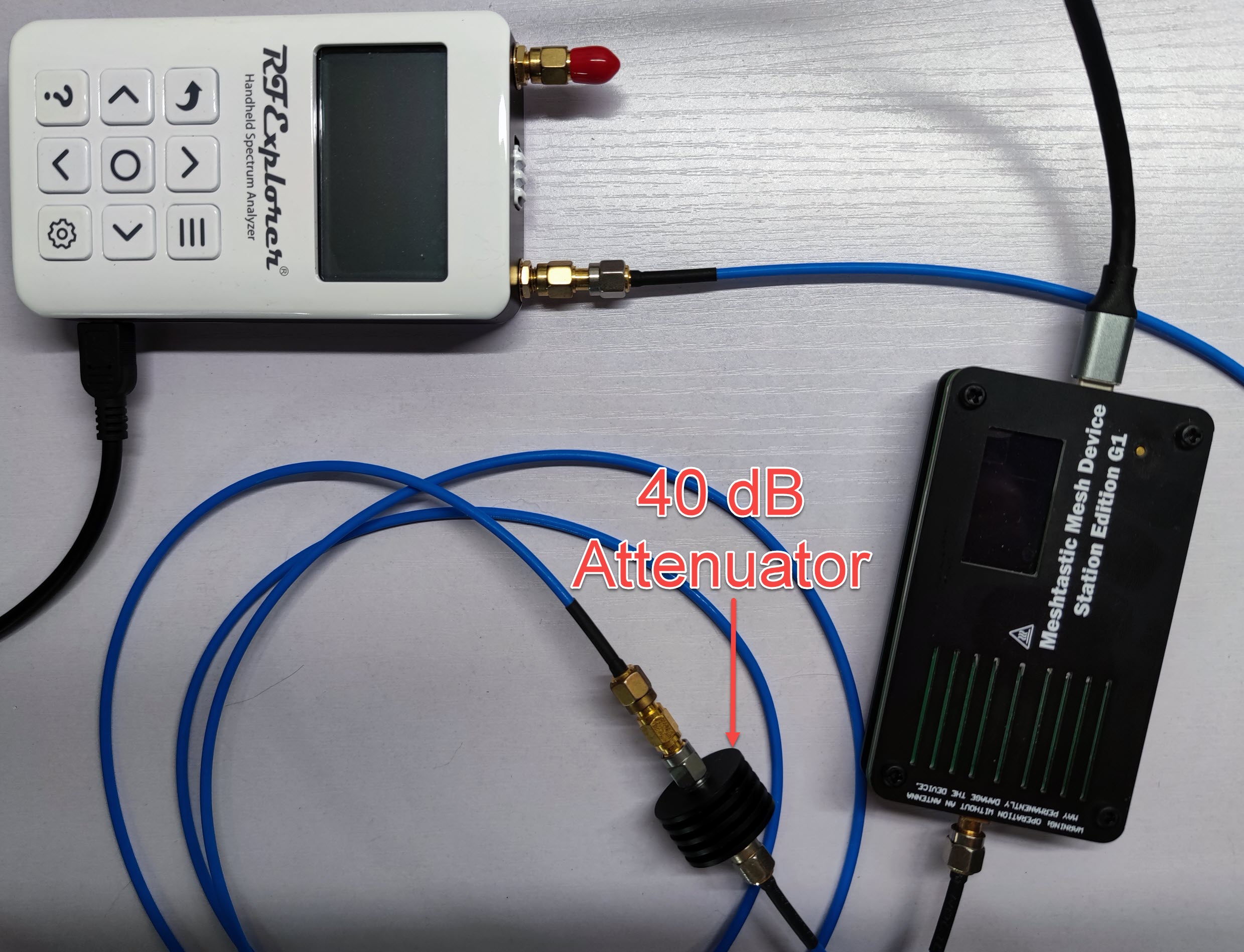 For Instrument Setup, RF Explorer 6G Combo PLUS Spectrum Analyzer and 40 dB Attenuator was used to measure the RF transismission power. Meshtastic firmware firmware_neil_station-g1-1.2.60.bin.zip was flashed into the DUT. Meshtastic Android APP 1.2.64 had been used to control the DUT with channel options = “Long Range / Slow” and Region = “US”.
Measurements
 When SX1262 TX set to 16 dBm, according to above result, the RF output power was 35.5 dBm, Gain = 19.5dB.
Repeat the measurement process with various SX1262 TX Power (TX Power Setting). The results were summarized in the follow table.
Summary for Conduction Test
| Region = “US” Center Frequency = 903.08 MHz | |||
|---|---|---|---|
| SX1262 TX Power Setting | PA Output Power | PA Gain | Description |
| 17 dBm | 35.5 dBm (3.55 W) | 18.5dB | |
| 16 dBm | 35.5 dBm (3.55 W) | 19.5dB | |
| 15 dBm | 35 dBm (3.16 W) | 20dB | |
| 14 dBm | 34.5 dBm (2.82 W) | 20.5dB | Recommended Setting, 1 dB Compression Point (P1dB) |
| 13 dBm | 33.5 dBm (2.24 W) | 20.5dB | |
| 12 dBm | 33 dBm (2 W) | 21dB | |
| 11 dBm | 32.5 dBm (1.78 W) | 21.5dB | |
| 10 dBm | 31.5 dBm (1.41 W) | 21.5dB | |
| 9 dBm | 30.5 dBm (1.12 W) | 21.5dB | |
| 8 dBm | 29.5 dBm (0.89 W) | 21.5dB | Default Setting, Operation with ISM band |
Accessories - 12V Battery Docker
Because Station Edition G1 could be powered by either USB Type C (PD Protocol with minimum 9V2A is required) or 2Pins Socket (Pitch=2.5mm, 8VDC-20VDC, 2A minimum). Power supply choice is very convenient, so that Battery Docker has been discontinued.
| Schematics for 12V Battery Docker | meshtastic_mesh_device_station_edition_12v_battery_docker_28_jul_2022.pdf | Version: 28 Jul 2022 |
12V Battery Docker is powered by USB TypeC with 15V PD Protocol. It has capability to charge 3*18650 Lithium Batteries with 2A MAX charging current. It also comes with multi protection features, such as Battery Temperature Monitoring, Overcharge/Overdischarge protection, Overcurrent Protection, etc.
While the Station G1 can be powered directly via USB TypeC, the 12V Battery Docker can still be used as backup power, or in scenarios that require mobility.
The motivation for designing the 12V Battery Docker is that most Power Banks cannot supply power to Station G1, because the Power Bank will automatically power off when the load is low in power consumption, especially when PD protocol is used. A few hundred mA would be considered as low in power consumption for most cases.


PCB
| No. | Description |
|---|---|
| 1 | 18650 Batteries |
| 2 | LED Indicator (Green) for fully charged status |
| 3 | LED Indicator (Red) for charging status |
| 4 | Li-ion Battery Protection Circuit based on XB3303A |
| 5 | NTC Thermistor, muRata NCP18XH103F03RB, 10kΩ ±1% 3380K |
| 6 | CN3703 Li-ion Battery Charger Controller |
| 7 | USB Type C Socket |
| 8 | CN1 Power Output Socket for Station G1, 1*2P, Pitch=2.5mm |
| 9 | CN3 is a duplicate of CN2 except IO35, 1*10P, Pitch=1.5mm, please refer to the schematic for more information. |
| 10 | CN2 is used to provide battery gauge function for Meshtastic if it is connected to CN2 of Station G1, 1*10P, Pitch=1.5mm |
| 11 | Power Switch for Station G1 |
Charging Status LEDs:
- Batteries are full charged when Green LED ON and Red LED OFF.
- Batteries are charging when Green LED OFF and Red LED ON.
- Green LED and Red LED are OFF at the same time indicates the 12V Battery Docker is powered up by voltage lower than 15V. Generally, this status indicates that the Type C Charger does not support 15V PD Protocol.
- Green LED and Red LED flashing at the same time indicates two possible problems. 1. At least one of three 18650 batteries is not installed properly or damaged. 2. The charging voltage is lower than the batteries voltage (12.6V MAX) which typically means your USB Type C Charger supports PD protocol but does not support PD 15V. In other words, it usually means that the output voltage of the USB Type C Charger has fallen back to 12V or 9V (determined by the maximum output voltage the USB Type C Charger supports), you may have to replace the USB Type C Charger with one which supports 15V PD Protocol.
Dimension
| Item | Description |
|---|---|
| Size | 10cm*9.6cm*2.7cm |
| Color | Black |
| Weight | ~65g (Without Batteries) |
Charging Experiment and Thermal Analysis

According to the charging profile in the CN3703’s datasheet, the highest temperature was expected to occur in the phase with the highest current, thus the highest temperature could be measured during the Constant Current Phase (2A for 12V Battery Docker).
For the charging experiment, three 2000 mAh 18650 Li-ion batteries was installed into 12V Battery Docker. The charging process used 1 hour and 23 minutes to charge the batteries’ voltage from 9.6V to 12.6V. About half an hour was Constant Current Phase, and the rest of the time was Constant Voltage Phase.
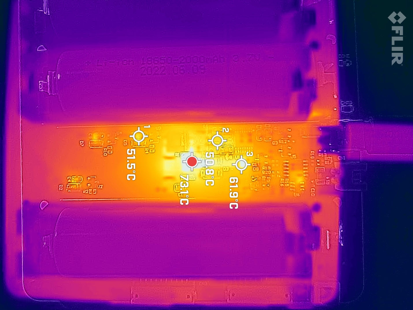
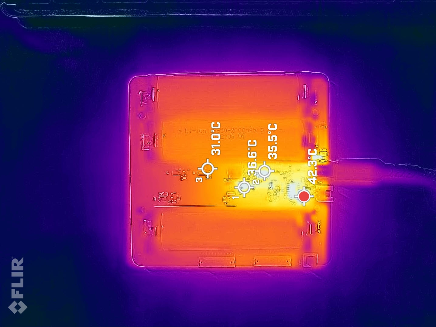
Thermal infrared image of the Constant Current Phase (Left) and the Constant Voltage Phase (Right), ambient temperature: 28 degrees in Celsius
Summary for Thermal Analysis
| Charging Time: 1 hour and 23 minutes, Ambient Temperature: 28 ℃ | ||
|---|---|---|
| Part No. | Constant Current Phase | Constant Voltage Phase |
| D1 | 73.1 ℃ | 36.6 ℃ |
| Q1 | 61.9 ℃ | 35.5 ℃ |
| U2,U3,U4 (XB3303A) | 51.5 ℃ | 31 ℃ |
| U1 (CN3703) | 50.8 ℃ | 35.5 ℃ |
Battery Gauge
The battery gauge will be automatically enabled within 30s if CN2 connector is connected to CN2 of Station G1.
 For Station G1, the battery voltage has been mapped from 0-12.6V.
Details
The battery characteristics are defined at Line 37 to Line 40 in the variant.h.
#define BAT_FULLVOLT 12600
#define BAT_EMPTYVOLT 8200
#define BAT_CHARGINGVOLT 12600
#define BAT_NOBATVOLT 6690
So that, Station G1 is expected to work with three Li-ion 18650 batteries, the full charged voltage = 12.6V, empty voltage = 8.2V.
Known Issues
The firmware will automatically turn off the device when detecting the battery voltage lower then 8.2V. On the other hand, the battery voltage will drop 0.X V when the PA is in transmission mode, because the PA will theoretically consume peak value of 1.2A@7.5V. Therefore, in daily use, you cannot wait for the battery voltage to drop to 8.2V before charging. The exact value of the voltage drop depends on the internal resistance of the batteries. Choosing batteries with lower internal resistance can alleviate the problem.
Warning
If you want to set the PA Output Power higher or equal to 33dBm. Please use the coaxial extension cable with magnetic base adapter included with product or any 50 ohm coaxial cable to keep the antenna at least 20cm away form the battery docker. Otherwise, the XB3303A Li-ion Battery Protection IC on the battery docker may be interfered and enter the protection state, so that Station G1 will be powered off. The power can be restored by reinstalling all batteries.
The Latest Firmware
Warning
When you install new firmware, the previous configuration may be lost. You may need to refer to TX Power Setting to set TX Power again.
Typical Settings
PA Output Power = 29.5 dBm
meshtastic --set lora.tx_power 8
PA Output Power = 34.5 dBm
meshtastic --set lora.tx_power 14
The Latest Firmware
Meshtastic Mesh Device Station Edition G1 had been supported by the official meshtastic repository on Github from firmware version 1.3.42. Thus, the latest firmware could be downloaded from the meshtastic project’s releases page: https://github.com/meshtastic/Meshtastic-device/releases
Firmware file: firmware-station-g1-1.x.x.bin
Following instructions to flash it to the Station g1: https://meshtastic.org/docs/getting-started/flashing-firmware/esp32/
Pre-compiled Firmware for Meshtastic 1.2.65
| Version | Date | Download | Description |
|---|---|---|---|
| 1.2.65 | 10-Aug-2022 | firmware-station-g1-1.2.65-Patch1.bin | Battery gauge for 12V Battery Docker is supported. Source Code |
| 1.2.60 | 28-Jun-2022 | firmware_neil_station-g1-1.2.60.bin.zip | Initial Release |
Software
Android
The Android APP could be downloaded and installed from the Google Play Store: https://play.google.com/store/apps/details?id=com.geeksville.mesh
APP Source Code: https://github.com/meshtastic/Meshtastic-Android/releases
iOS
The iOS APP could be downloaded and installed from following URL: https://meshtastic.org/docs/software/apple
JS/Python/Web Interface
Javascript, Python, Web Interface are also supported by the Meshtastic. More information: https://meshtastic.org/docs/software
Advanced Topics
TX Power Setting
For Meshtastic Firmware 2.x.x
Prerequisites
Execute following command by using Meshtastic CLI, this operation will set the SX1262 TX Power to 14 dBm:
meshtastic --set lora.tx_power 14
Output:
Connected to radio
Set lora.tx_power to 14
Writing modified preferences to device
Verification, execute following command:
meshtastic --get lora.tx_power
Output:
Connected to radio

lora.tx_power: 14
Completed getting preferences
According to the Summary for Conduction Test, the PA Output Power is expected to be 34.5 dBm (2.82 W), after executing above command.
For Meshtastic Firmware 1.2.x
Prerequisites
Execute following command by using Meshtastic CLI, this operation will set the SX1262 TX Power to 14 dBm:
meshtastic --ch-set tx_power 14 --ch-index 0
Output:
Connected to radio
Set tx_power to 14
Writing modified channels to device
Verification, execute following command:
meshtastic --info
Output:
Connected to radio
...
Channels:
  PRIMARY psk=default { "txPower": 14, "modemConfig": "Bw125Cr48Sf4096", "psk": "AQ==" }
...
According to the Summary for Conduction Test, the PA Output Power is expected to be 34.5 dBm (2.82 W), after executing above command.
Real World Testing
FCC Rules and Regulations
Operation with ISM band
Any RF device can transmit encrypted data in the ISM bands without license. However, the maximum transmitter power fed into the antenna should be less than or equal to 30dBm (1W).
| ISM Bands |
|---|
| 902 to 928 MHz |
| 2.400 to 2.4835 GHz |
| 5.725 to 5.875 GHz |
Benefit from high power PA even when operating in the ISM bands. For example, if there is a long coaxial cable between the transmitter and the antenna, the coaxial cable may have considerable insertion loss. At this time, the transmitting power of the transmitter can be increased to ensure exactly 30dBm power feeding into the antenna.
Reference
- FCC Rules for Unlicensed Wireless Equipment operating in the ISM bands. Retrieved Jun 1, 2022, from https://afar.net/tutorials/fcc-rules/
Operation with Amateur Radio License
Lora 915MHz is exactly 33cm band in the amateur bands. With Amateur Radio License, according to the National Association for Amateur Radio's description, the transmitter can transmit unencrypted data using up to 1500W.
This official document describes in detail how to turn off Meshtastic's encryption: Licensed (HAM) Operation.
How to increase the Lora RF output power: TX Power Setting
 Copyright: The National Association for Amateur Radio
Reference
- US Amateur Radio Frequency Allocations. Retrieved Jun 1, 2022, from http://www.arrl.org/frequency-allocations
- US Amateur Radio Technician Privileges. Retrieved Jun 1, 2022, from http://www.arrl.org/files/file/Tech%20Band%20Chart/US%20Amateur%20Radio%20Technician%20Privileges.pdf
- Amateur Radio Allocations and Overlapping Part 15 Bands - An Overview and a Part 97 versus Part 15 and Permissible Power Comparison. Retrieved Jun 28, 2022, from https://www.qsl.net/kb9mwr/projects/wireless/allocations.html