Relay I/O Board is widely used in applications of smart home project. In this article, I will detail how to control the Relay I/O board using Raspberry Pi with Raspberry Pi Universal Expansion Board via internet. The codes and schematic diagrams used in this article was listed at the end of this article.
Part I: Hardware
1. Pin Mapping
The CPLD on the Raspberry Pi Universal Expansion Board can be used to map pins between modules. For this project, we want to map pins as following diagram Fig.1. 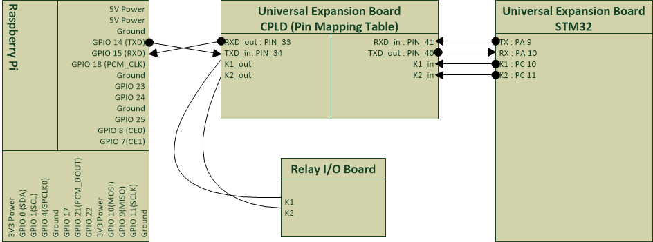
This part is pretty easy since we only need to map the UART1 of the STM32 to the Raspberry Pi and PC10, PC11 of the STM32 to the Relay I/O board using the CPLD. The following Verilog code can implement the idea:
module RS232(RXD_in,TXD_in,RXD_out,TXD_out,
K1_in,K1_out,K2_in,K2_out);

input   RXD_in, TXD_in,K1_in,K2_in;
output  RXD_out,TXD_out,K1_out,K2_out;

assign RXD_out = RXD_in;
assign TXD_out = TXD_in;

//assign pins for relays K1 and K2
assign K1_out = K1_in;
assign K2_out = K2_in;

endmodule
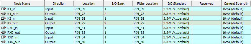
Navigate to Quartus -> Assignments -> Pin Planner. The IO need to be configured as following picture.
We can flash the design into the CPLD right now.
2. STM32 Configuration
Creating a new .c source code file RelayIOBoard.c as the driver of the Relay I/O board:
/*Driver for Relay IO board*/
#include < stm32f10x.h>
#include < stdio.h>

#define on  1
#define off 0

int k1_state;
int k2_state;

void Relay(int relay_num, int on_off){
  switch( relay_num )
  {
    case 1:
			//For K1 which is controlled by the PC10
        if(on_off == on)
				{
         GPIO_SetBits(GPIOC, GPIO_Pin_10);
				 k1_state = on;
        }
        if(on_off == off)
				{
         GPIO_ResetBits(GPIOC, GPIO_Pin_10);
				 k1_state = off;
        }
        break;
    case 2 :
			//For K2 which is controlled by the PC11
        if(on_off == on)
				{
         GPIO_SetBits(GPIOC, GPIO_Pin_11);
				 k2_state = on;
        }
        if(on_off == off)
				{
         GPIO_ResetBits(GPIOC, GPIO_Pin_11);
				 k2_state = off;
        }
        break;
  }
}

void Get_Relay_States(void){
   if(k1_state == on){
      printf("k1on\r\n");
   }
	 else{
      printf("k1off\r\n");
   }
   if(k2_state == on){
      printf("k2on\r\n");
   }
	 else{
      printf("k2off\r\n");
   }
}

void Relay_init(void )
{
  Relay(1,off);
	Relay(2,off);
	k1_state =off;
	k2_state =off;
}
We need to add following commands to the Shell() in CommandShell.c:
	 //Command K1 on
	 if(IsStringMatch(Command,"k1on",Counter)){
		  Relay(1, 1);
		 printf("k1on\r\n");
	   }
	 //Command K1 off
	 if(IsStringMatch(Command,"k1off",Counter)){
		  Relay(1, 0);
		 printf("k1off\r\n");
	   }
	 //Command K2 on
	 if(IsStringMatch(Command,"k2on",Counter)){
		  Relay(2, 1);
		 printf("k2on\r\n");
	   }
	 //Command K2 off
	 if(IsStringMatch(Command,"k2off",Counter)){
		  Relay(2, 0);
		 printf("k2off\r\n");
	   }
	 //Command krs, get relay states
	 if(IsStringMatch(Command,"krs",Counter)){
		  Get_Relay_States();
	   }
For convenience, the Firmware STM32_Relay_1.0.hex needs to be flashed into the MCU. The Firmware will host a Command Shell on UART1. It also includes the driver of the Relay I/O board.
3. Testing
Connecting Relay I/O Board to the Pmod1 socket on the Raspberry Pi Universal Expansion Board. A cooling fan may be controlled by the relay as following figure. 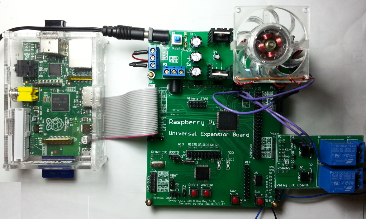
Entering following command in the Linux shell of the Raspberry Pi:
minicom -b 9600 -o -D /dev/ttyAMA0
Try k1on, k1off, k2on and k2off commands to control the relays.
Part II: Software
- Prerequisites: Accessing serial port via CGI script
1. Web API Design In above section, a batch of commands was implemented which could control the relay I/O board via UART port. Typically, the UART port is only reachable locally, but our plan is controlling the relays through internet, thus we need to design a Web API using CGI and python, this Web API will act as a bridge between internet and local UART port.
| API | Parameters | Returns | Description |
|---|---|---|---|
| cgi/relaycfg.py | k state | kXoff kXon Note: X is the number of the corresponding relay. | This API accept two parameters k and state. k is the number of the relay, it can be assigned to k1 or k2. state can be assigned to on, off or query. When state is assigned to on or off, the corresponding relay will be turned on or turned off. When state is assigned to query, the current state of the corresponding relay will be returned. |
e.g.: cgi/relaycfg.py?k=k2&state=off  cgi/relaycfg.py?k=k2&state=on
 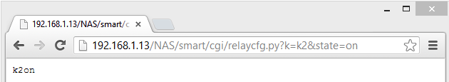 cgi/relaycfg.py?k=k2&state=query
 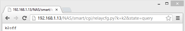 Or
Or 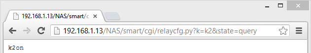 The source code of this API was provided in Part III.
2. UI Design
The UI was implemented using jQuery mobile and AJAX technology.
Screenshots
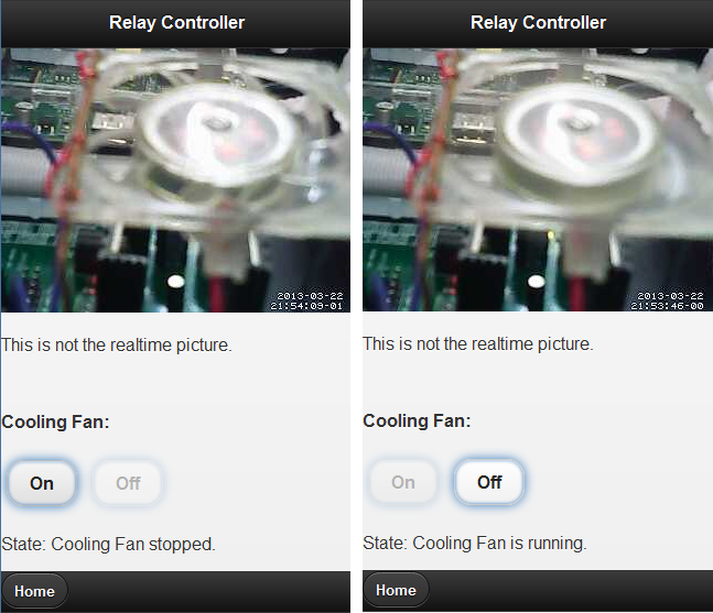
Important features:
- cgi/relaycfg.py?k=k2&state=query will be executed just after the DOM is fully loaded. This operation will return the current status of relay k2 (Cooling Fan). The buttons will be enabled or disabled and the State will also be updated according to the current status of k2.
- The buttons will be enabled or disabled and the State will also be updated during the operation. The source code of this UI design was provided in Part III.
Part III: Resource