Prerequisites:
Using Serial Port with MAX 3232 Pmod Board
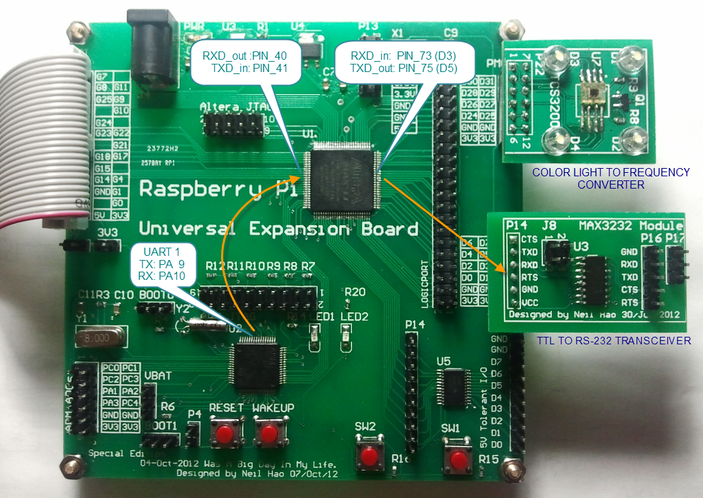
Our goal is connecting the STM32 MCU (STM32F103RBT6) to the Computer’s Serial Port via the onboard CPLD(EPM240T100C5) and the MAX 3232 Pmod Board. In the beginning, the MAX 3232 Pmod Board should be attached to the Universal Expansion Board as the picture shown below:
- STM32 Configuration
The Firmware STM32Project_FW3.5-UEB-RS232Test.zip need to be flashed into the MCU. The Firmware will host a Command Shell on UART1.
- CPLD Configuration
This part is pretty easy since we only need to map the UART1 to the MAX 3232 Pmod using the CPLD. The following Verilog code can implement the idea:
module RS232(RXD_in,TXD_in,RXD_out,TXD_out);
input RXD_in, TXD_in;
output RXD_out,TXD_out;
assign RXD_out = RXD_in;
assign TXD_out = TXD_in;
endmodule
Navigate to Quartus -> Assignments -> Pin Planner. The IO need to be configured as following picture.
We can flash the design into the CPLD right now.
- Testing
Connecting the MAX 3232 Pmod Bord to the Serial Port of the computer, the LOGICPORT Logic Analyzer could also be attached to the Universal Expansion Board.
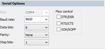
Configure the Serial Port Terminal Software (e.g. SecureCRT) as the picture shown below:
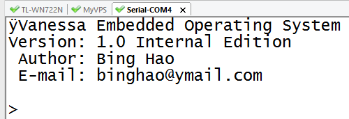
We almost reach the final stage, let us turn on the board. The Serial Port Terminal will print out following information:
The RS232 data stream should also be sniffed by the Logic Analyzer.


